
Available fault current describes what the electrical system can deliver at a particular location. Interrupting rating describes the fault current a fuse or circuit breaker can interrupt at its rated voltage under specified test conditions. Short-circuit current rating, or SCCR, describes the prospective fault current to which equipment can be connected under its evaluated conditions. These are related values, but they belong to different objects and are not interchangeable.
For a fully rated arrangement, two separate comparisons are needed:
[
I_{\text{interrupting rating}} \geq I_{\text{available at device}}
]
[
I_{\text{equipment SCCR}} \geq I_{\text{available at equipment}}
]
Both comparisons require compatible voltage, current definitions, and application conditions. A breaker with an adequate interrupting rating does not establish an adequate SCCR for the equipment containing it. Documented series-rated combinations require a different application review rather than an exception inferred from these numbers alone.
What Each Value Describes
| Value | What it belongs to | What it tells you | Where to obtain it |
|---|---|---|---|
| Available fault current | A specific point in the electrical system, under defined source and operating conditions | The prospective fault current the system can deliver at that point | A short-circuit study or documented calculation using applicable source and distribution data |
| Interrupting rating | A fuse, circuit breaker, or evaluated protective-device combination | The fault current the device or combination can interrupt at the specified voltage and test conditions | Device markings, exact-model manufacturer data, and applicable combination-rating documentation |
| SCCR | A component or complete equipment assembly | The prospective fault current associated with its evaluated short-circuit capability and protection conditions | Equipment nameplate, manufacturer documentation, or an applicable documented SCCR determination |
UL’s panelboard and circuit-breaker application guides distinguish the protective device’s interrupting rating from the assembly’s short-circuit rating. Eaton’s discussion of available fault current distinguishes both equipment ratings from the system condition at the installation point.
The relationship is therefore:
- The system establishes the available fault current.
- The protective device must have an applicable interrupting capability.
- The equipment must have an applicable short-circuit rating.
Increasing one equipment rating does not automatically increase the other. UL specifically notes that installing a breaker with an interrupting rating higher than the end-use equipment’s marked short-circuit rating does not raise the overall combination above the equipment’s lower rating.
An SCCR also does not promise that equipment will remain undamaged or return immediately to service after a fault. It relates to defined short-circuit acceptance criteria, not unrestricted fault endurance.
Establish Available Fault Current at the Correct Location
Start with the short-circuit study result for the equipment terminals or bus being evaluated. A utility fault-current value at the service point is source information; it is not automatically the available fault current at every downstream panel or machine.
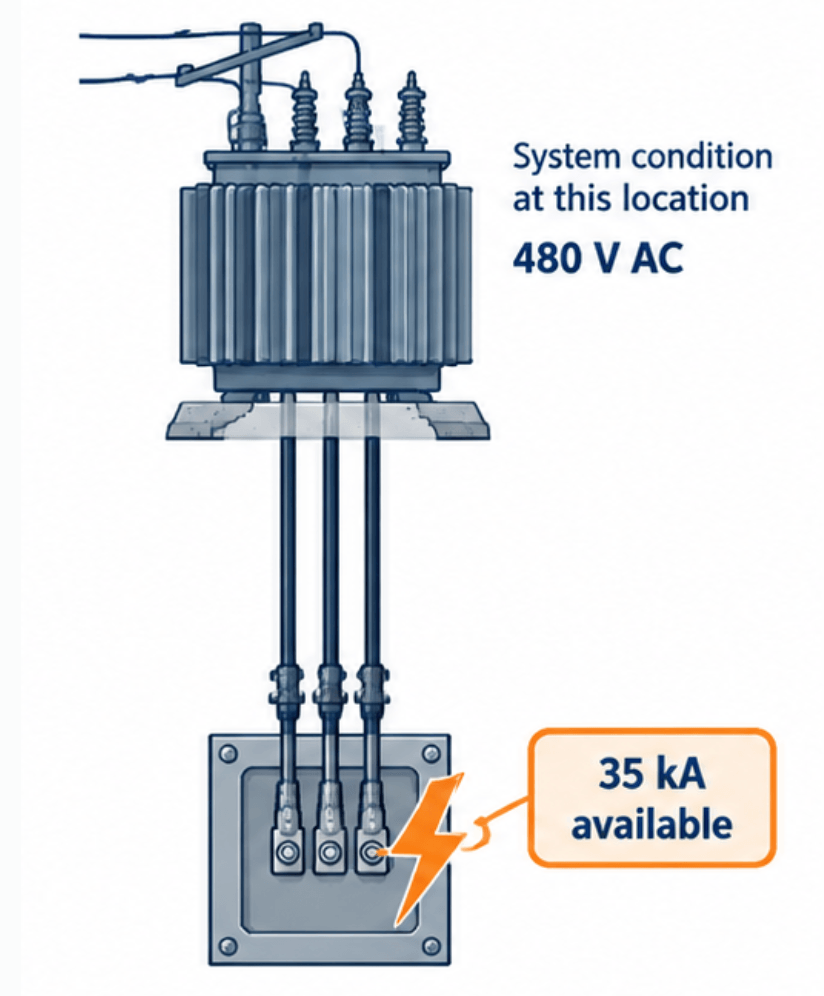
Eaton’s published explanation describes a point-to-point process: establish the source fault level, account for the conductors or busway to the next location, and repeat for downstream equipment. Its calculation guidance also identifies transformer impedance and motor contribution as relevant inputs.
For a usable comparison, retain the following information with the fault-current value:
- The bus or terminal identification.
- System voltage and AC or DC designation.
- Fault type and current basis, such as three-phase RMS symmetrical current.
- Source configuration represented by the result.
- Calculation date and the distribution arrangement on which it depends.
- Whether applicable local sources and motor contributions were included.
Do not substitute operating load current, a breaker’s ampere rating, or a transformer’s full-load current for available fault current. Transformer load current and impedance can be inputs to a fault calculation, but load current alone is not the result.
A value copied from an existing label is useful only if its supporting calculation still represents the installation. Transformer replacement, distribution changes, and equipment relocation can change the available fault current and require the rating comparison to be revisited.
For a machine with multiple facility supplies, evaluate each relevant supply connection. UL’s machinery guidance, written around the 2021 edition of NFPA 79, explains that the available fault current must be known at the line terminals of each machine supply-circuit disconnecting means. One supply’s result does not establish the conditions at another supply.
Read the Protective Device Rating Without Confusing It With Load Amperes
A circuit breaker may display several current-related values: frame rating, trip rating or setting, and interrupting rating. They answer different questions.
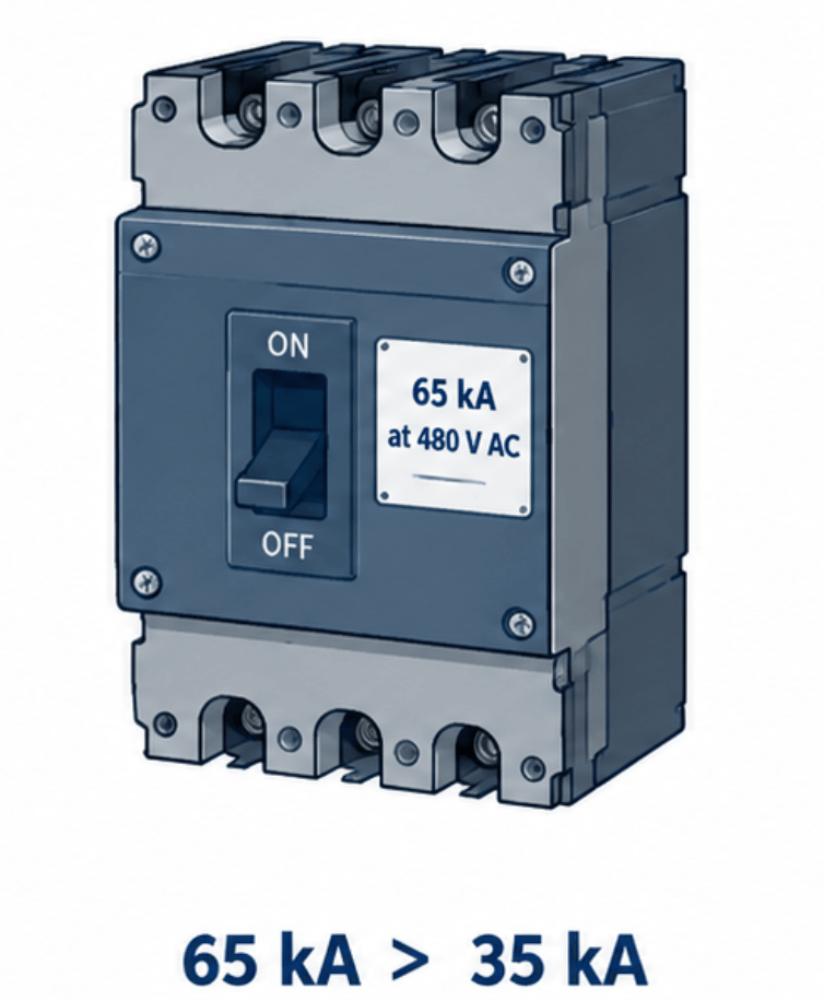
For example, a hypothetical breaker marked “100 A” and “65 kA RMS symmetrical at 480 V AC” has a 100 A current rating and a 65,000 A interrupting rating at the stated voltage. Neither marking says that the system actually has 65 kA available.
UL’s molded-case circuit-breaker marking guide identifies ampere rating and interrupting rating as separate markings. It also states that when multiple interrupting ratings apply at different voltages, the corresponding voltage-current pairs are marked together. Use the rating applicable to the actual circuit voltage—not the largest kA number printed on the device.
Record:
- Manufacturer and complete catalog or type designation.
- Applicable voltage rating.
- Interrupting rating at that voltage.
- AC or DC applicability and relevant frequency.
- Any required wiring arrangement or combination-rating reference.
Voltage configuration matters as well as voltage magnitude. For example, UL distinguishes a straight 480 V rating from a 480Y/277 V slash rating: the slash-rated breaker is subject to both the higher circuit-voltage limit and the lower voltage-to-ground limit. It is not a universal substitute for a straight-rated breaker on every nominal 480 V system.
“AIC” and “kAIC” are common industry shorthand for interrupting capacity expressed in amperes or kiloamperes. The formal rating and its voltage conditions still control; the shorthand does not identify the equipment assembly’s SCCR.
Read the Equipment SCCR and All Associated Conditions
Look for the assembly nameplate or manufacturer’s rating label, not just the main breaker label. For a panelboard, UL identifies the marking “Short-Circuit Current Rating” with a value in RMS symmetrical amperes. The equipment may have different ratings at different voltages or ratings dependent on specified protective devices.
A complete reading includes:
- The SCCR value and associated voltage.
- The equipment identity and installed configuration.
- Any specified upstream or integral protective device.
- Maximum protective-device ampere rating.
- Required fuse class or breaker manufacturer and type.
- References to combination tables, wiring diagrams, or installation instructions.
A conditional marking might state that equipment is suitable for a specified fault level only when protected by a particular fuse class, maximum fuse size, or identified breaker. Those conditions are part of the rating, not optional installation preferences. UL’s panelboard guide provides examples of this type of marking.
Component SCCRs and assembly SCCR must also remain distinct. A high-rated disconnect, terminal block, or contactor does not establish the rating of the entire control panel. UL identifies UL 508A Supplement SB as a method used to determine SCCR for UL Listed industrial machinery; Eaton describes its separate steps for component ratings, feeder components, and overall equipment SCCR. Applying that method requires the actual component and protection information, not a visual estimate from the largest device.
If the assembly rating cannot be established from its marking and supporting documentation, the assembly comparison remains unresolved. The main breaker’s interrupting rating is not a substitute.
Match the Conditions Before Comparing kA Values
A numerical comparison is meaningful only after the values describe compatible conditions.
| Check | What must agree or be verified |
|---|---|
| Location | The available fault current applies to the device or equipment point being evaluated. |
| Voltage | The selected interrupting rating and SCCR apply at the circuit voltage. |
| System configuration | Grounding arrangement, phase configuration, and any slash-voltage restrictions are satisfied. |
| Current basis | RMS symmetrical, peak, and asymmetrical quantities are not treated as interchangeable. |
| AC or DC | The rating applies to the actual current type and required connection arrangement. |
| Protective conditions | Required fuse class, breaker type, maximum size, and other rating conditions match the installation. |
| Assembly configuration | Installed or replacement devices are permitted by the equipment documentation. |
These checks follow the distinctions and marking conditions described in UL’s circuit-breaker and panelboard application guides.
In particular, a peak let-through current is not the same quantity as an RMS symmetrical available fault current. A current-limiting device may reduce fault-current peak and let-through energy within its current-limiting range, but its curves and application conditions must be used through an applicable evaluation method. A bare comparison between a peak-current number and an RMS SCCR number does not establish equipment suitability.
For equipment carrying IEC ratings, retain the manufacturer’s terminology. Schneider Electric identifies (I_{cu}) as rated ultimate short-circuit breaking capacity and (I_{cs}) as rated service short-circuit breaking capacity under IEC 60947-2. Do not silently relabel either value as a UL interrupting rating or an assembly SCCR; use the product’s applicable certification and installation requirements.
Worked Comparison: Adequate Breaker Rating, Inadequate Equipment SCCR
Consider these hypothetical inputs, all assumed applicable to the same 480 V AC installation and expressed on a compatible RMS symmetrical basis:
| Input | Assumed value | Assumed source |
|---|---|---|
| Available fault current at the equipment supply terminals | 35 kA | Project short-circuit study |
| Main breaker interrupting rating at 480 V AC | 65 kA | Exact breaker marking |
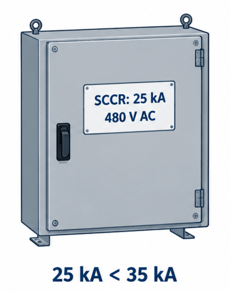
| Equipment assembly SCCR at 480 V AC | 25 kA | Assembly nameplate |
Assume no applicable series rating or alternative conditional assembly rating has been established.
For the breaker:
[
65-35=30\text{ kA}
]
The breaker’s interrupting rating exceeds the entered available fault current by 30 kA.
For the assembly:
[
25-35=-10\text{ kA}
]
The assembly SCCR is 10 kA below the available fault current. The breaker comparison is numerically satisfactory, but the assembly comparison is not. The 65 kA breaker does not convert the 25 kA assembly into 65 kA equipment. This distinction is consistent with UL’s explicit limitation on using a higher-rated breaker in lower-rated end-use equipment.
The differences are arithmetic results, not predictions of damage or extra usable capacity. A 30 kA positive difference does not establish coordination, acceptable clearing time, or arc-flash performance.
When Series Ratings or Current-Limiting Protection Change the Review
A fully rated arrangement uses protective devices with individual interrupting ratings adequate for their application points. A series-rated arrangement instead relies on an applicable combination in which a downstream breaker’s individual interrupting rating can be lower than the available fault current.
UL’s panelboard guide describes series-combination markings that identify the line-side device, load-side breakers, voltage, and combination rating. The rating belongs to the specified combination; it cannot be inferred merely because the upstream device has a higher interrupting rating.
Before relying on a series rating, verify the exact equipment and device combination, applicable voltage, manufacturer documentation, and installation restrictions. Eaton’s series-rating manual also identifies motor-contribution restrictions as part of the application review.
Series rating and increasing a control panel’s SCCR are not interchangeable procedures. UL’s machinery guidance explains that applying series ratings to address an inadequate machine SCCR involves additional calculation or testing considerations and is not a preferred general solution.
Likewise, installing a current-limiting fuse or breaker upstream does not automatically establish a higher permissible fault level for downstream equipment. Any claimed benefit must be supported by the applicable component combinations, manufacturer data, and SCCR evaluation method. UL specifically cautions that simply adding current-limiting protection does not guarantee adequate panel or machine protection.
Use the Interrupting Rating Comparison Tool for the Arithmetic Step
The Interrupting Rating Comparison tool compares a short-circuit study result with an entered device interrupting rating. Its published description identifies it as an arithmetic comparison, not a determination of equipment suitability or code compliance.
Use an established available fault-current result and the applicable device rating on the same unit basis:
[
1\text{ kA}=1{,}000\text{ A}
]
For the example above, the device comparison uses 35 kA available and a 65 kA interrupting rating. The separate 25 kA assembly SCCR still requires its own review. A calculator cannot supply missing nameplate conditions, establish an undocumented series combination, or confirm that the study represents the present system.
Keep the final record specific: identify the study location and configuration, the device rating and voltage, the assembly SCCR and its conditions, and any combination documentation relied upon. For U.S. projects, determine the locally adopted NEC edition and amendments before making a compliance finding. The manufacturer and UL application guidance cited here explains the rating relationships; it does not establish which code edition governs a particular installation.